

Archive for June 2013
BACK TO BASICS: MECHANICAL SEALS EXPLAINED
INTRODUCTION
Because mechanical shaft seal failures are the number one cause of pump downtime, we decided to dedicate this column to mechanical seal basics.
Years ago, most pump shafts were sealed using rings of soft packing, compressed by a packing gland, but this type of shaft seal required a fair amount of leakage just to lubricate the packing and keep it cool. Then came the development of the “mechanical seal,” which accomplishes the job of restraining product leakage around the pump shaft with two very flat surfaces (one stationary and one rotating). Even though these mechanical seal faces also require some (very small) leakage across the faces, to form a hydrodynamic film, this leakage normally evaporates and is not noticeable. Most pump shafts today are sealed by means of mechanical seals. However, because of the delicate components used for this new sealing method, mechanical seal failures are the greatest cause of pump down time. This begs for a better understanding of this seal type and its application.
THE BASICS
 |
| FIGURE 1 |
 |
| FIGURE 2 |
Mechanical seals are leakage control devices, which are found on rotating equipment such as pumps and mixers to prevent the leakage of liquids and gases from escaping into the environment. Figure 1 above shows a typical centrifugal pump, which highlights its constituent parts, including the mechanical seal.
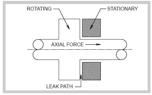
A mechanical seal consists of 2 principle components. One component is stationary and the other rotates against it to achieve a seal (Figure 2). There are many types of mechanical seal, ranging from simple single spring designs to considerably more complex cartridge seal types. The design, arrangement and materials of construction are essentially determined by the pressure, temperature, speed of rotation and product being sealed(the product media).
THE DESIGN
 |
| FIGURE 3 |
By way of example, a simple mechanical seal design has 7 components (Fig 3):
1. Stationary component; commonly referred to as the seat .
2. Stationary component sealing member.
3. Rotating component.
4. Rotating component sealing member.
5. Spring.
6. Gland plate.
7. Clamp ring.
THE SEALING POINTS
A mechanical seal has 4 main sealing points (indicated by orange circles as per Figure 3):
I. The seal between the rotating (3) and stationary faces (1). This is known as the primary seal.
II. The seal between the stationary member (1) and stuffing box face, i.e. Gasket (2).
III. The seal between the rotating member and shaft or shaft sleeve (4). This is known as the secondary seal and may be an o -ring as shown, a v -ring, a wedge or any similar sealing ring.
IV. The seal between the gland plate and stuffing box, this is usually a gasket, or o -ring.
3 of the 4 main sealing points need little explanation, but consideration is required for the sealing point between the rotating and stationary components (faces). This primary seal is the basis of a mechanical seal design, and is what makes it work.
The rotating component (3) and stationary component (1) are pressed against each other, usually by means of spring force.
The mating faces of both components are precision machined (lapped) to be extremely flat within 2 light bands, which is an optical method of measuring flatness). (usually to
This flatness minimizes leakage to a degree where it is essentially negligible. In fact, there is leakage between these faces but it is minute and appears as a vapour. (for immediate consideration)
Spring compression (usually) provides initial face pressure. This pressure is maintained when the seal is at rest via the spring(s) thus preventing leakage between the faces
FLUID FILM
If the mechanical seal faces rotated against each other without some form of lubrication they would wear out (and the seal would fail) due to face friction and the resultant heat generated. So, lubrication is required which for simplicity, is supplied by the product media. This is known as fluid film and maintaining its stability is of prime importance if the seal is to provide satisfactory and reliable service.
The primary disadvantage of this seal type is that it is prone to secondary seal hang-up and fretting of the shaft or sleeve, especially when the seal is exposed to solids. A pusher seal type should not be selected if the secondary seal is likely to hang-up. Can small deposits of solids form ahead of the secondary sealing member?
MECHANICAL SEAL TYPES
There are multiple designs available for the mechanical seal configuration. Understanding how they work will help the readers select the appropriate type for their application.
They are:

- Conventional
- Pusher
- Non-pusher
- Unbalanced
- Balanced
- Cartridge
PUSHER SEALS incorporate secondary seals that move axially along a shaft or sleeve to maintain contact at the seal faces, to accommodate wear and to assist in the absorption of shaft misalignment.

Advantages are that they are inexpensive and commercially available in a wide range of sizes and configurations.
NON-PUSHER OR BELLOWS SEAL does not have a secondary seal that must move along the shaft or sleeve to maintain seal face contact. In a non-pusher seal the secondary seal is in a static state at all times, even when the pump is in operation. A secondary sealing member is not required to make up the travel as the rotary and stationary seal faces wear. Primary seal face wear is typically accommodated by welded metal or elastomeric bellows which move to assist in the compression of the rotary to stationary seal faces.
The advantages of this seal type are the ability to handle high and low temperature applications (metal bellows), and that it does not require a rotating secondary seal, which means it is not prone to secondary seal hang-up or shaft/sleeve fretting. Elastomeric bellows seals are commonly used for water applications.

The disadvantages are that thin bellows cross sections must be upgraded for use in corrosive environments, plus the higher cost of metal bellows seals.
CARTRIDGE SEALS have the mechanical seal pre-mounted on a sleeve (including the gland). They fit directly over the shaft or shaft sleeve, and are available in single, double, and tandem configurations. Best of class pump users give strong consideration to the use of cartridge seals.
The advantages are that this seal configuration eliminates the requirement for seal setting measurements at installation. Cartridge seals lower maintenance costs and reduce seal setting errors.

The primary disadvantage is the higher cost, plus in some cases they will not fit into existing stuffing box/seal housings.
MECHANICAL SEALS ARRANGEMENTS
Single seals do not always meet the shaft sealing requirements of today’s pumps, due to the small amount of required leakage when handling toxic or hazardous liquids; suspended abrasives or corrosives in the pumpage getting between the seal faces and causing premature wear; and/or the potential for dry operation of the seal faces. To address these situations, the seal industry has developed configurations which incorporate two sets of sealing faces, with a clean barrier fluid injected between these two sets of seal faces. The decision to choose between a double or single seal comes down to the initial cost to purchase the seal vs. the cost of operation, maintenance and downtime caused by the seal, plus the environmental and user plant emission standards for leakage from the seal.
The more common multiple seal configuration is called a Double (dual pressurized) seal, where the two seal face sets are oriented in opposite directions. The features of this seal arrangement are:
- Potentially five times the life of a single seal in severe environments.
- The metal inner seal parts are never exposed to the liquid product being pumped, which means no need for expensive metallurgy; especially good for viscous, abrasive, or thermosetting liquids.
- The double seal life is virtually unaffected by process upset conditions during pump operation.

The other multiple seal configuration is called a Tandem (dual unpressurized) arrangement, where the two individual seals are positioned in the same direction. This seal arrangement is commonly used in Submersible wastewater pumps, between the pump and motor, with oil as the barrier liquid. The typical features of this seal arrangement are:
- The pressure between seals is lower than the seal chamber pressure (typically atmospheric)
- The external fluid only lubricates the most outside set of faces
- Pumped fluid lubricates most inside faces
- The outside seal serves as a safety seal or containment device
- Leakage to the atmosphere is external fluid, possibly mixed with small amounts of pumped fluid.
MECHANICAL SEAL SELECTION
The proper selection of a mechanical seal can be made only if the full operating conditions are known. Identification of the exact liquid to be handled is the first step in seal selection.
- Metal parts must be corrosion resistant, usually plated steel, bronze, stainless steel, or Hastelloy.
- Mating faces must also resist corrosion and wear. Carbon, ceramic, silicon carbide or tungsten carbide may be considered.
- Stationary sealing members of Buna, EPR, Viton and Teflon are common.
Pressure: The proper type of seal, balanced or unbalanced, is based on the pressure on the seal and on the seal size.
Temperature: Can determine the use of the sealing members as materials must be selected to handle liquid temperature.
Characteristics of the Liquid: Abrasive liquids create excessive wear and shorten seal life.
- Double seals, or clear liquid flushing from an external source, allow the use of mechanical seals on these difficult liquids.
- For best results with double (or tandem) seals handling abrasive, the inboard seal faces should be a hard material, such as silicon carbide vs. silicon carbide, while the outboard seal faces should have maximum lubricity, such as silicon carbide vs. carbon graphite.
CONCLUSIONS
The seal type and arrangement selected must meet the desired reliability, life cycle costs, and emission standards for the pump application. Double seals and double gas barrier seals are becoming the seals of choice. Finally, it should be noted that there are special single seal housing designs that greatly minimize the abrasives reaching the seal faces, even without an external water flush, but this is a subject for another column.
SOME DEFINITIONS RELATED TO FUELS & NEW GENERATION LAWS

Additives
Chemicals added to fuel in very small quantities to improve and maintain fuel quality and/or to lower emissions.
After treatment Devices
Devices which remove pollutants from exhaust gases after the gas leaves combustion chamber (e.g., catalytic converters or diesel particulate filters). The term “exhaust gas after treatment” is considered derogatory by some in the emission control industry, but there is no consensus on the use of such alternatives as “post-combustion treatment” or “exhaust emission control
Air Quality Management District (AQMD)
Administrative districts organized in California to control air pollution. Nationwide in the U.S., AQMDs are parallel to the areas designated for classification against the National Ambient Air Quality Standards (NAAQS). Generally, AQMDs and their national parallel encompass multiple jurisdictions and closely follow the definition of Consolidated Metropolitan Statistical Areas and Metropolitan Statistical Areas.
Air Toxics
Toxic air pollutants, as classified by pertinent regulations. Examples of substances classified as air toxics by the US Clean Air Act include acetaldehyde, benzene, 1,3-butadiene, formaldehyde, and polycyclic organic matter (POM). California air toxics regulations also classify diesel exhaust particulates as a toxic air contaminant.
Alternative Fuel
Fuel other than petroleum diesel or gasoline.
American Society for Testing and Materials (ASTM)
A non-profit organization that establishes specifications and standard test methods for a broad range of materials and products. ASTM standards are recognized as definitive guidelines for quality of motor fuels.
Biodiesel
The mono alkyl esters of long chain fatty acids derived from renewable lipid feedstock, such as vegetable oils and animal fats, for use in compression ignition (diesel) engines. Manufactured by transestrification of the organic feedstock by methanol.
Brake Specific Fuel Consumption (BSFC)
BSFC is the ratio of the engine fuel consumption to the engine power output (as measured at the flywheel). BSFC has units of grams of fuel per kilowatt-hour (g/kWh) or pounds mass of fuel per brake horsepower-hour (lb/bhp-hr). BSFC is a measure of engine efficiency.
California Air Resources Board (CARB)
A state regulatory agency charged with regulating the air quality in California.
Carcinogens
Substances known to cause cancer.
Catalyst
A substance which influences the rate of a chemical reaction but is not one of the original reactants or final products, i.e. it is not consumed or altered in the reaction. Catalysts are used in many processes in the chemical and petroleum industries. Emission control catalysts are used to promote reactions that change exhaust pollutants from internal combustion engines into harmless substances.
Cetane Index
A calculated value, derived from fuel density and volatility, giving a reasonably close approximation to cetane number.
Cetane Number
A measure of ignition quality of diesel fuel. The higher the cetane number the easier the fuel ignites when injected into an engine. Cetane number is determined by an engine test using two reference fuel blends of known cetane numbers. The reference fuels are prepared by blending normal cetane (n-hexadecane), having a value of 100, with heptamethyl nonane, having a value of 15.

Clean Air Act (CAA)
In the U.S., the fundamental legislation to control air pollution. The original Clean Air Act was signed in 1963. The law set emissions standards for stationary sources, such as factories and power plants. Criteria pollutants included lead, ozone, CO, SO2, NOx and PM, as well as air toxics. The CAA was amended several times, most recently in 1990. The Amendments of 1970 introduced motor vehicle emission standards for automobiles and trucks
Cloud Point (CP)
A measure of the ability of a diesel fuel to operate under cold weather conditions. Defined as the temperature at which wax first becomes visible when diesel fuel is cooled under standardized test conditions (ASTM D2500).
Evaporative Emissions
Hydrocarbon vapors that escape from a fuel storage tank or a vehicle fuel tank or vehicle fuel system.
Injection Period
The time, measured in degrees of crankshaft rotation, between the beginning and end of injection. On engines with hydro mechanical injection systems, it is controlled by the opening and closing of ports in the injector body or by the action of a plunger forcing fuel out of a cup. On electronic injection systems, it is determined directly or indirectly by the action of a solenoid valve.
Liquefied Natural Gas (LNG)
Natural gas that has been refrigerated to cryonic temperatures where the gas condenses into a liquid.
Liquefied Petroleum Gas (LPG)
Liquefied Petroleum Gas (LPG) is a mixture of low-boiling hydrocarbons that exists in a liquid state at ambient temperatures when under moderate pressures (less than 1.5 MPa or 200 psi). LPG is a by-product from the processing of natural gas and from petroleum refining. Major components of LPG are propane (min. 85% content in the U.S.), butane and propylene.
Natural Gas (NG)
A mixture of hydrocarbon compounds and small quantities of various non hydrocarbon components existing in the gas phase or in solution with crude oil in natural underground reservoirs. The main component of natural gas is methane.
Nitrogen Oxides (NOx)
Several air-polluting gases composed of nitrogen and oxygen which play an important role in the formation of photochemical smog. Nitrogen oxides are collectively referred to as “NOx”, where “x” represents a changing proportion of oxygen to nitrogen. Internal combustion engines are significant contributors to the worldwide nitrogen oxide emissions. For the purpose of emission regulations, NOx is composed of colorless nitric oxide (NO), and the reddish-brown, very toxic and reactive nitrogen dioxide (NO2). Other nitrogen oxides, such as nitrous oxide N2O (the anesthetic “laughing gas”), are not regulated emissions.
NMHC
Non-Methane Hydrocarbons.
NMOG
Non-Methane Organic Gases.
Ozone (O3)
An oxygen molecule with three oxygen atoms. The stratosphere ozone layer, which is a concentration of ozone molecules located at 10 to 50 kilometers above sea level, is in a state of dynamic equilibrium. Oxygen molecules absorb ultraviolet (UV) light to form ozone which, in turn, decomposes back to oxygen. These processes absorb most of the ultraviolet light from the sun, shielding life from the harmful effects of UV radiation. Ozone is normally present at ground level in low concentrations. In cities where high level of air pollutants is present, the action of the sun’s ultraviolet light can, through a complex series of reactions, produces harmful concentrations of the ground level ozone. The resulting air pollution is known as photochemical smog.
Particulate Matter (PM)
Particles formed by incomplete combustion of fuel. Compression ignition (diesel) engines generate significantly higher PM emissions than spark ignited engines. The particles are composed of elemental carbon, heavy hydrocarbons (SOF), and hydrated sulfuric acid (“sulfate particulates”).
Pour Point
A measure of the ability of a diesel fuel to operate under cold weather conditions. Defined as the temperature at which the amount of wax out of solution is sufficient to gel the fuel when tested under standard conditions (ASTM D97).
Propane (C3H8)
A normally gaseous straight-chain hydrocarbon. Propane is a colorless paraffinic gas that boils at a temperature of -42°C. It is extracted from natural gas or refinery gas streams.
Renewable Energy
Energy obtained from sources that are essentially inexhaustible, unlike fossil fuels. It includes conventional hydro-electric, wood, bio-feedstock, waste, geothermal, wind, photovoltaic, and solar thermal energy.
Selective Catalytic Reduction (SCR)
Term frequently used as a synonym for catalytic reduction of NOx in diesel exhaust or flue gases by nitrogen containing compounds, such as ammonia or urea. Such SCR systems are commercially available for stationary applications and are being developed for mobile diesel engines. Since “selective catalytic reduction” is a generic term which also applies to other reactions, its use may lead to confusion in some situations.

Tag :
ASTM,
fuels,
HFO,
LNG,
LPG,
marine,
marine fuels,
MARPOL,
MDO,
MGO,
NOx,
Pour Point,
Propulsion,
sailors' diaries,
SCR,
ship,
SOLAS
TO DETERMINE B.O.D. OF EFFLUENT FROM SEWAGE TREATMENT PLANT
Biochemical oxygen demand or B.O.D is the amount of dissolved oxygen needed by aerobic biological organisms in a body of water to break down organic material present in a given water sample at certain temperature over a specific time period. The term also refers to a chemical procedure for determining this amount. This is not a precise quantitative test, although it is widely used as an indication of the organic quality of water.
The BOD value is most commonly expressed in milligrams of oxygen consumed per litre of sample during 5 days of incubation at 20 °C and is often used as a robust surrogate of the degree of organic pollution of water.
BOD can be used as a gauge of the effectiveness of wastewater treatment plants. It is listed as a conventional pollutant in the U.S. Clean Water Act.
BOD is similar in function to chemical oxygen demand (COD), in that both measure the amount of organic compounds in water. However, COD is less specific, since it measures everything that can be chemically oxidized, rather than just levels of biologically active organic matter.
PRINCIPLE
The Biochemical Oxygen Demand (B.O.D.) of sewage or of polluted water is the amount of oxygen required for the biological decomposition of dissolved organic matter to occur under aerobic condition and at the standardised time and temperature. Usually, the time is taken as 5 days and the temperature 20°C as per the global standard.
The B.O.D. test is among the most important method in sanitary analysis to determine the polluting power, or strength of sewage, industrial wastes or polluted water. It serves as a measure of the amount of clean diluting water required for the successful disposal of sewage by dilution. The test has its widest application in measuring waste loading to treatment plants and in evaluating the efficiency of such treatment systems.
The test consists in taking the given sample in suitable concentrations in dilute water in B.O.D. bottles. Two bottles are taken for each concentration and three concentrations are used for each sample. One set of bottles is incubated in a B.O.D. incubator for 5 days at 20°C; the dissolved oxygen (initial) content (D1) in the other set of bottles will be determined immediately. At the end of 5 days, the dissolved oxygen content (D2) in the incubated set of bottles is determined.
Then, mg/L B.O.D. =(D1 – D2 ) / P
where,
P = decimal fraction of sample used.
D1 = dissolved oxygen of diluted sample (mg/L), immediately after preparation.
D2 = dissolved oxygen of diluted sample (mg/L), at the end of 5 days incubation.
Among the three values of B.O.D. obtained for a sample select that dilution showing the residual dissolved oxygen of at least 1 mg/L and a depletion of at least 2 mg/L. If two or more dilutions are showing the same condition then select the B.O.D. value obtained by that dilution in which the maximum dissolved oxygen depletion is obtained.

Sample Calculation
D1 = Initial Dissolved Oxygen = ...... mg/L
D2 = Dissolved Oxygen at the end of 5 days = ...... mg/L
P = Decimal fraction of sample used = ......
Therefore, mg/L of B.O.D. =(D1 – D2 )/P = ......

GREETINGS ON THE DAY OF SEAFARER

This is the day for us to take pride in what we do - keeping the world alive and running. No matter what people on the land perceive us as, we can never change their negative and narrow mindsets. Simply, because they are ignorant, they know nothing about us! There can be no biggest compliment for our deeds than seeing the world alive and growing!
We belong to the breed that puts discipline and hard work at the pinnacle of performance. While there can be millions who dress up in their Armani suits and ride their Mercs and BMWs to their plush offices, but when we dress every morning in our worksuits, what we carry on our shoulders is even more gigantic and noble responsibility - “keeping the world alive". Those stripes on our shoulders are much more than mere glitzy fabric - they are the testimony of perseverance and ability to perform under situations - one in Merc or BMW can never imagine! A
nd while we do that, there will be hearts missing us much more than they do for others, there will be pairs of eyes who will be longing to see us more desperately than they would do for others, there will be mothers waiting to see their sons, there will be a baby waiting for his father’s first touch & there will be the “Queen" who dons many hats while she battles the world alone while her “King” is away. Of course, no one else can understand what it means to be one among the “Chosen Ones" or the loved ones of the Chosen ones - they rightly say - You need to be One, to know one!
Congratulations & wishing #pride & #glory to each of our #sailor brotherhood, & #respect to their queens, children and families, #takeabow!
May the Almighty protect us, our families and bless us with the prosperity & glory of the seas! Amen!
With Best Regards,
The Admin, Sailors' Diaries
THE FIRST POST
My fellow seafarers #regards and #respect!
What we are starting today is a very modest initiative and minimal efforts, but indeed, with a profound vision. A lot of thinking and time has gone together with few heads with diverse and intelligent heads put together. Choosing the name has been one of the aspect that has taken a lot of our time and mental faculties -but keeping in mind that we aim to create an appeal to a larger community we come up with a name - Sailors’ Diaries!
So, Ladies & Gentleman - play the drumroll …
We present you a resourcefully ambitious and exciting -
SAILORS’ DIARIES
While there has been a lot of thinking and planning gone into at the drawing board, we slowly aim to make it large! MARK THE DATE - 25TH OF JUNE IN THE YEAR 2013 - IMO DAY OF THE SEAFARER! And what can be a more remarkable day than releasing this blog & going live ON a day that is meant for the ones for whom this blog is meant for - The Noble Seafarers! Sailors’ Diaries is dedicated for you all Sailors’ and your families and loved ones on the “DAY OF THE SEAFARER" We plan to further add pages, for News, Nautical Section, Marine Engineering Branch, Safety & Environmental section & Downloads. Further we plan to involve plenty to social interaction, by creating pages for our less celebrated heros - The family, wives & children of the Seafarers, do visit our Sailors’ Kids & Sailor Queens section to contribute and share your ideas . Of course we are planning for larger social initiatives. Do get in touch with the Administrator in case of any thing you want to ask or share. We are looking forward for your co-operation & participation.
Thank you & Safe Sails,
The Admin, Sailors’ Diaries


